Saturday, June 15, 2013

Cat and Dog Repellent Circuit Diagram

Cat and Dog Repellent Circuit Diagram

The electronic dog repellent circuit diagram below is a high output ultrasonic transmitter which is primarily intended to act as a dog and cat repellent. The ultrasonic dog repellant uses a standard 555 timer IC1 set up as an oscillator using a single RC network to give a 40 kHz square wave with equal mark/space ratio. This frequency is above the hearing threshold for humans but is known to be irritating frequency for dog and cats.
Cat and Dog Repellent Circuit Diagram
Since the maximum current that a 555 timer can supply is 200mA an amplifier stage was required so a high-power H-bridge network was devised, formed by 4 transistors TR1 to TR4. A second timer IC2 forms a buffer amplifier that feeds one input of the H-bridge driver, with an inverted waveform to that of IC1 output being fed to the opposite input of the H-bridge which can be seen at A & B in an oscilloscope.
Get more information on various electrical projects, embedded projects, electronics projects, communication projects by visiting this blog regularly.


With this cool cat/dog repeller circuit you could chase the cats  off  from any where you want. In fact, I designed this circuit to chase my cat from my computer table. Most of the animals like cats respond violently to ultrasonic sound and in fact it’s the best way to chase them off. This principle is employed in this circuit.
The circuit here is nothing but an astable multivibrator wired around NE555 (IC1). The cat repellent circuit produces an ultrasonic sound in the range 15-20Khz. The NE 555 is enough to drive a small piezo buzzer and no amplification stages are needed. The POT R2 can be used to adjust the frequency of sound.
Cat Repeller Circuit diagram with Parts list. 
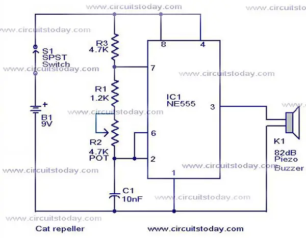
cat-repeller-circuit.JPG
Notes.
  • The circuit can be powered from a 9V battery or the power can be tapped from your computer SMPS.
  • The circuit can be assembled  on a general purpose PCB.
Authors view. 
I do not guarantee the full effectiveness of the circuit.You have try a lot of frequency settings to make your cat feel discomfort at last. More over the cat may get accustomed to the sound after some time. For me the circuit was only a partial success  and now my cat feels nothing even if the speaker is placed in it’s ear.You try your luck. Best of luck.

Tuesday, June 4, 2013

PC Temperature Controller


Here is a simple temperature controller that turns your personnel computer (PC) off when the temperature of the PC increases beyond the optimal temperature value. Some of the larger integrated circuits become quite hot and if the temperature inside the PC becomes too high, these devices may not be able to dissipate heat fast enough. This, in turn, could lead to failure of devices and eventually of the PC.

Let us assume that the maximum working temperature of your PC is 55°C. So for safe working of your PC, this temperature controller uses a temperature sensor (LM35) and a comparator (CA3140) which disconnect the PC from the power supply whenever the temperature of your PC rises above 55°C. This threshold value is user-adjustable and can be set anywhere between 0°C and 100°C.

Fig. 1: Temperature controller circuit 
Fig. 1 shows the circuit of the PC temperature controller, while Fig. 2 shows pin configurations of the components used. The circuit works off 9V DC, which is derived from main power as follows: Mains power supply is rectified by a bridge rectifier comprising diodes D1 through D4, divided by a resistor network comprising R1 and R2, and stabilised by zener diode ZD1. Capacitor C1 filters the ripples.

Using preset VR1 you can set the reference voltage. The reference voltage at non-inverting pin 3 of the comparator is set such that the temperature of the PC is 55°C. When the temperature of the PC is below 55°C, the voltage at the inverting input (pin 2) of IC2 is lower than the voltage at the non-inverting input (pin 3). At this stage, the comparator output at pin 6 of IC2 is high. This high output triggers triac 1 (BT136), providing mains power to operate the PC.

Fig. 2: Pin configurations of components
When the temperature of the PC increases above 55°C, the inverting input (pin 2) of IC2 also goes above the non-inverting input (reference voltage) at pin 3 and hence the comparator output goes low. This stops triggering of triac 1 (BT136) preventing mains power supply from reaching the PC.

Thus this arrangement provides mains voltage to the PC at temperature of up to 55°C and stops when the temperature goes above 55°C.

Assemble the circuit on any general-purpose PCB in the form of a PC expansion card, so you can use it as an add-on card to any PC. Plug it in, switch-on the supply and use your computer with safety temperature device.